


PART10Power Supply Circuit
Experiment 2 :Fixed Voltage Regulator
Theory
Generally, precision type constant voltage power supply is designed to protect overload by controlling the constant current. For example, if the electric current over 1A flows through the machine with the constant voltage load of 30V and there is possibility of of damages, the setting for constant current can be changed as 1A and the damage can be prevented.
Fig. 10-11 is the basic circuit that has function of constant voltage and constant current mode.
In this circuit, with Amp-1 in the center, RMV is the constant voltage circuit, and standard voltage source(VRef) is used common to Amp-2. In this circuit, D1 and D2 are used for the outputs of Amp-1 and Amp-2 not to be interconnected, and are operated as OR Gate for the input of Tr2. And since Amp-1 and Amp-2 are connected with the diode of same direction, Rb is used for the base bias of Tr2. Regulation Transistor Tr1 is darlington connected with Tr2.(In the actual experiment circuit, it is driven as darlington connection as in this circuit.) However, in the experiment circuit for fixed voltage output, simpler circuit as in fig. 10-12 is used.
tab1Experiment 10-2.1 Constant Voltage Circuit Experiment (In Circuit-1, 2 of M10, compose a circuit as in fig 10-12.)
1.Connection(Circuit-1,2 of M-10)
1.Circuit Connection
5.1V Zener Diode(D1) Connection; Connect between 2d terminal and 2f terminal of Circuit-2 with yellow line.
Constant Voltage fVoltage indication window and Circuit Connection: Connect between 1j terminal of Circuit-1 and 2a terminal of Circuit-2 with red line, and between 1n terminal and 2b terminal of Circuit-2 with black line.
2.Power Connection
Connect between Variable Power V1 terminal on the left of M10 board and 1a terminal of Circuit-1 with red line, and between COM terminal and 1b terminal with black line.
3.Measuring Instrument Connection
Voltmeter Connection
Input Voltage Measurement Connection: Connect between 2i terminal of Circuit-2 and A+ terminal of Signal Input CH A on the front panel of Multimeter with red line, and between 2o terminal and A- terminal with black line.
2.Wiring Diagram
flash
3.Measurement
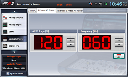
- 1Choose variable power at Touch LCD panel, and click 3 Phase AC Range Power tab.
Click at the right of AC Voltage indication window and make it as 12.0V.
Click and apply the output of 3 Phase AC Range Power to the input of Circuit-1.
- 2Measure the output wave form and effective voltage with no-load.
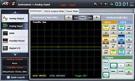
Choose analog input on the front panel.
Draw the wave form indicated in Oscilloscope screen in table 10-4.
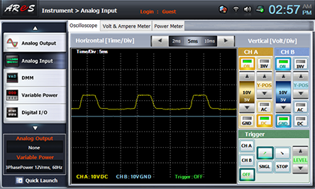
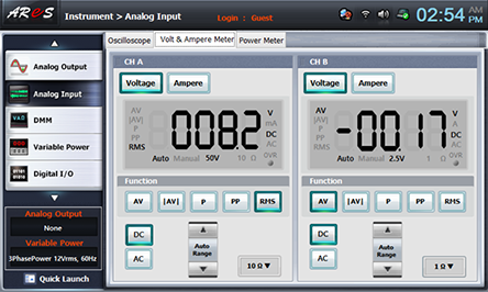
Choose Volt & Ampere Meter tab, click , , at CH A and record the measured output voltage in the relevant column of table 10-4. (CH B is not used.)
- 3Measure the output wave form and effective voltage with load.
120 Ω Load Connection: Connect between 2h terminal and 2j terminal of Circuit-2, and between 2l terminal and 2n terminal with blue lines.
Wiring Diagram
flash
Draw the wave form indicated in Oscilloscope screen in table 10-4.
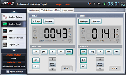
Record the measured value in Volt & Ampere Meter screen in the relevant column of table 10-4.
After the measurement, click variable power and click to cut off AC 12V output.
- 4Measure by connecting Zener diode(D2).
Zener Diode D2 Connection: Change the connection from 2d terminal to 2f terminal of Circuit-2 to 2g terminal.
Execute the measurement process 2), 3) above and record the measured result in the relevant column of table 10-4.
After the measurement, click variable power and click to cut off AC 12V output.