PART16Signal Converter
Experiment 3 :F/V Converter
Theory
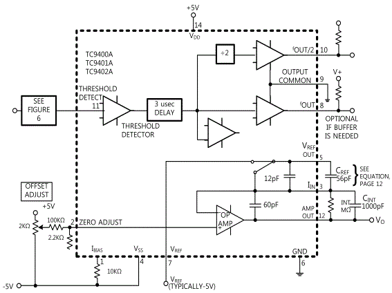
Frequency-Voltage converter changes the input frequency to proportional DC voltage output and fig.16-10 is a F-V converter that operates to DC~10KHz. In fig.16-10, the converter generates the output voltage which is linearly proportional to the input frequency waveform. At the input of the comparator, if FIN is “0”, the output of comparator becomes “0” and is distributed to the summing connection circuit of OP AMP and this value flows in turn through feedback resistance which generates voltage pulse at the output of OP AMP. The condenser(CINT) applied to. RINT averages this pulse and changes it to DC voltage which is linearly proportional to the input frequency. In this circuit, the relationship between input frequency and output voltage is as below.
![V_OUT=[V_REF∙C_REF∙R_INT ] F_IN](../image/part16/formal16.6.gif)
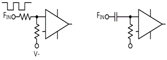
The response speed to the change of FIN is determined by RINT and CINT, and the sum of ripples included in VOUT is inversely proportional to CINT and input frequency. If CINT is increased, the ripple can be decreased and 1μF~100μF is proper value for low frequency. When this circuit is operated with single power, VREF voltage is determined by the voltage difference between OFFSET input terminal (+) of OP AMP and VREF terminal connected to SW. If the input signal is smaller than ±200㎷, the comparator cannot read this signal so the input at least bigger than this should be applied. Also, If you want to use the input frequency up to maximum 100kHz, the value of RINT should be changed as lower than 100㏀. If unipolar input signal is used, as in fig.16-11, it could be used by applying the resistance circuit used in OFFSET circuit or connecting the connection condenser.
f0 and f0/2 are normally not used in F-V mode. If the buffer is connected to this output as additional circuit and it is applied a little bit, f0 will follow the input waveform. However, f0 will be delayed 3㎲ to FIN, and one cycle of frequency output f0 in the circuit will be half cycle of f0/2.
The IC used in F-V converter circuit is TC9400, and fig.16-11 expresses DC-10KHz F/V converter circuit.
Experiment Process
1. For the experiment, use Circuit-3 of M-16.
2. Connect between 3a-3b, 3f-3g terminals and adjust R5 so that the output voltage becomes 0V.
3. Measure the output voltage when the frequency of input signal is increased by 100Hz to 3a-3b as in table 16-3 and record the result in the relevant column and test the linearity of input frequency and output voltage. Here, input level should be 1V~3V.
tab1Experiment 16-3.1 F/V Converter Circuit (Compose as Circuit-3 of M16.)
1.Connection
1.Circuit Connection
In Circuit-3 of M16, connect between 3f-3g terminals with yellow line.
2.Power connection is internally connected.
3.Measuring Instrument Connection
Voltmeter Connection(Freq. Input
Connect between 3a terminal of Circuit-3 and A+ terminal of Signal Output on the front panel with red line, and between 3b terminal and A- terminal with black line.
Voltmeter Connection(V-OUT)
On the Multimeter of front panel, connect between High terminal and 3h terminal of Circuit-3 with red line, and between Low terminal and 3i terminal with black line.
2.Wiring Diagram
3.Measurement
- 1Adjust the Offset.
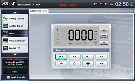
Choose dmm at Touch LCD, click and connect between 3a-3b terminals of Circuit-3 with yellow line and adjust the output voltage to become 0V.
- 2Output the square wave 100Hz, 3Vrms
Remove the yellow line connection between 3a-3b terminals of Circuit-3, connect BNC terminal to Signal Output of front panel, and connect red lead wire to 3a terminal and black lead wire to 3b terminal.
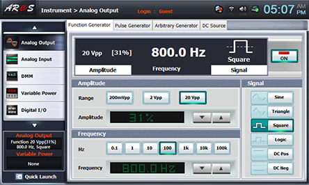
Choose Function Generator at Touch LCD, choose at Amplitude, adjust Amplitude as amplitude 31% by clicking and set up the Frequency as , Signal as and click to apply the output frequency to the circuit.
Choose analog output at Touch LCD, click Volt & Ampere Meter tab and choose , , at CH A and check out if the output voltage of 100Hz is 3Vrms.
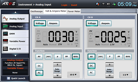
Choose dmm at Touch LCD, click quick launch at the bottom left and click of 100hz at Frequency of function window to increase the frequency by 100HZ as in table 16-3. Measure the output voltage of its dmm indication value and record it in the relevant column of the table and test the linearity of input frequency and output voltage.
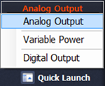
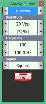
- 3Click to cut off the frequency applied to Freq. Input of Circuit-3.
4.Calculation
1. Calculate the output voltage following the formula below and record the result in the relevant column of table 16-3.
In Circuit-3, RINT=R7, CREF=C2, VREF=-5V.
VOUT=[VREF∙CREF∙RINT]FIN
Experiment Result Report
1. Experiment Result Table
2. Review and Explanation
1) Calculate the output voltage.
VOUT=[VREF∙CREF∙RINT]FIN


