PART8Operation Amplifier Circuit(OP AMP)
Experiment 2 :DC Offset
Theory
In case of ideal OP-Amp, if input voltage is “0”, out voltage is “0”. However, real OP-Amp has a little bit of output voltage. That is, even though the input is earthed, the output does not become “0” completely. This DC output voltage is called output offset voltage. The offset voltage can be expressed as below.
- Input offset current
- Input bias current
- Input offset voltage
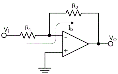
Input bias current should be applied to two inputs(+, - terminals) of OP-Amp so that OP-Amp can be operated properly. In the inverting amplifier of fig. 8-6, input bias current can flow through two input terminals and feedback resistance without the input signal. When the current flows through the resistance according to Ohm’s law, it is applied to both ends of two resistances. (V=IR)
Here, non-inverting input of OP-Amp is earthed, so the voltage is expressed as DC input voltage at both ends of this resistance, and this is amplified by OP-Amp. The output voltage(VOS) of inverting amplifier circuit in fig. 8-6 is occurred as a result of input bias current(Ib).

General way to calibrate output offset voltage caused by input bias current is to insert the resistance R3 between non-inverting (+) input terminal and the earthing, as in fig. 8-7. This additional resistance is same as the parallel combination of R1 and R2.

Therefore, the voltage between R3’s both ends is same as the voltage between both ends of parallel combined resistance of R1 andR1, and the polarity is opposite. Because two voltages have same sizes and opposite polarities, they set off each other. However, this means the bias current flowing on two input terminals are same. Unfortunately, in general OP-Amp, two bias currents are not exactly same, and the value Ib becomes the average of two input bias currents. Because there is the difference between two bias currents called input offset current IOS, there exists a little bit of DC output offset voltage and it is as below.

The other cause of output offset voltage is caused by input offset voltage of OP-Amp, and this is caused by the mismatches of inner circuit and outer circuit of OP-Amp.
The output offset above is to solve the existence of output voltage even when there is no input. However, in some cases, DC offset output is needed so circuit-2 or circuit-3 of M-08 can be used.
As in fig. 8-8, the input offset voltage Voi to non-inverting amplifier circuit can be expressed as connecting the battery in series to non-inverting (+) input of ideal OP-Amp. In the circuit of fig. 8-8, DC output offset voltage is calculated as the result of input offset voltage.
![V_OS=[1+R2/R1] V_oi](../image/part8/formal8.8.gif)
Experiment 8-2.1 Offset Experiment (Compose as Circuit-2, Circuit-3 of M-08.)
Inverting Amplifier
1.Connection(Circuit-2 of M-08)
1.Power Connection
It is connected internally.
2.Measuring Instrument Connection
Function Generator Connection
Plug in BNC cable to BNC terminal of Signal Output on front panel and connect red line to 2a terminal of Circuit-2, and black line to 2b terminal.
Voltmeter Connection
Connect between 2a terminal of Circuit-2 and A+ terminal of Signal Input CH A on the front panel of Multimeter with red line, and between 2b terminal and A- terminal with black line.
Connect between 2e terminal of Circuit-2 and B+ terminal of Signal Input CH B on the front panel of Multimeter with red line, and between 2f terminal and B- terminal with black line.
Separate Digital Multimeter Connection
Choose DC voltage measurement range of separate Digital Multimeter and connect red line to 2e terminal of circuit-2 and black line to 2f terminal.
2.Wiring Diagram
3.Measurement
Measuring Square Wave of 200 mVp-p 1kHz
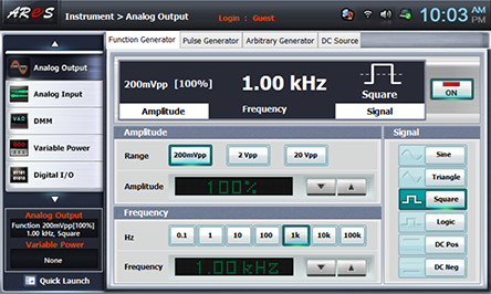
- 1Choose analog output at Touch LCD panel, click Function Generator and set up Amplitude Range as , Amplitude as amplitude 100%.
Set up Signal as , and choose and set up Frequency as 1kHz and click to apply the output of Function Generator to input of Circuit-2.
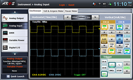
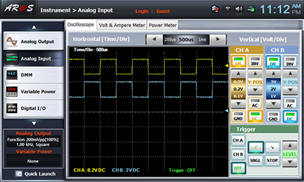
- 2Choose analog input at Touch LCD panel and set up at Oscilloscope tab as the picture below and change R5 so the output offset voltage becomes 0V.

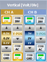

Adjust Y-POS of CH A and Y-POS of CH B so that the marker can be located as in the picture below.

- 3Measurement by Output Offset Voltage Setting
Change R5 and make the output offset voltage as the value in table 8-3 and draw the output wave form.
Measuring Sine Wave of 100mV(rms)
- 1Choose analog output at Touch LCD panel, click Function Generator and set up Amplitude Range as , Amplitude as amplitude 15%.
Set up Signal as , and choose and set up Frequency as 1khz and click to apply the output of Function Generator to input of Circuit-2.
Changing 100mV(rms) as mVpp can be done by the formula below.
2VPP=Vrms×2√2=100mV×2×1.414=282.8mVPP
15% of 2Vpp set up above is 300mVpp so it is set up as the approximate value of 100mV(rms).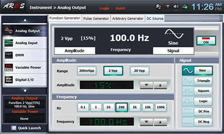
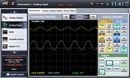
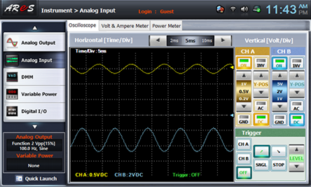
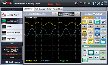
- 2Choose analog input at Touch LCD panel and set up at Oscilloscope tab as the picture below and change R5 so the output offset voltage becomes 0V.


Adjust Y-POS of CH A and Y-POS of CH B so that the marker can be located as in the picture below.
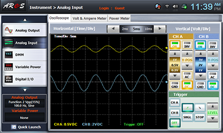
- 3Measurement by Output Offset Voltage Setting
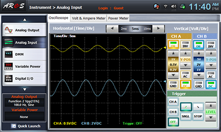
Change R5 and make the output offset voltage as the value in table 8-4 and draw the output wave form.
Non-inverting Amplifier
1.Connection(Circuit-3 of M-08)
1.Power Connection
It is connected internally.
2.Measuring Instrument Connection
Function Generator Connection
Plug in BNC cable to BNC terminal of Signal Output on front panel and connect red line to 3a terminal of Circuit-3, and black line to 3b terminal.
Signal Input Connection
Connect between 3a terminal of Circuit-3 and A+ terminal of Signal Input CH A on the front panel of Multimeter with red line, and between 3b terminal and A- terminal with black line.
Connect between 3c terminal of Circuit-3 and B+ terminal of Signal Input CH B on the front panel of Multimeter with red line, and between 3d terminal and B- terminal with black line.
Separate Digital Multimeter Connection
Choose DC voltage measurement range of separate Digital Multimeter and connect red line to 3c terminal of circuit-3 and black line to 3d terminal.
2.Wiring Diagram
3.Measurement
- 1It is same as [Inverting Amplifier]>[Measuring Square Wave of 200 mVp-p 1kHz] and draw the output wave form in the relevant column of table 8-3.
- 2It is same as [Inverting Amplifier]>[Measuring Sine Wave of 100mV(rms) 100Hz] and draw the output wave form in the relevant column of table 8-4.
Experiment Result Report
1. Experiment Result Table
2. Review and Explanation
Describe DC offset.


