PART14Sequential Logic Circuit
Experiment 2 :JK Flip-Flop
Theory
JK flip-flop is an improved version of clock part RS flip-flop from which the negative status is removed and constant value is output. The input J and K, just as input S and R, makes the flip-flop as set and as clear(J corresponds to set, and K corresponds to clear.) When 1 is applied to J and K at the same time, the flip-flop takes the complement of current status after one CP(In case of clock part SR flip-flop, it was negative status). That is, if Q(t)=1, Q(t+1)=0, and if Q(t)=0, Q(t+1)=1.
Fig.14-4(a) is the logic circuit of clock part JK flip-flop. In this fig., output Q makes K and CP input as AND and make the flip-flop as clear during the next CP when the previous status of Q is “1”. In the same way, output Q makes J and CP input as AND and the flip-flop as set during the next CP when the previous status of Q is “1”.
Operation of JK Flip-Flop
As in the characteristic table of fig.14-4(c), the operation of JK flip-flop is same as that of RS flip-flop except the case when J and K are all 1. When J and K are all 1, the CP is delivered through AND gate only, that is, the gate where output “1”of current flip-flop is feedback from the input. For example, if Q(t)=1, the output of upper AND gate becomes “1” and the flip-flop becomes clear status [Q(t+1)=0]. In any case, the next output status of flip-flop takes the complement of current status. Therefore, it is JK flip-flop that improves the unstable status of RS flip-flop. The symbol of JK flip-flop is as fig.14-4(b) and the flip-flop to which PR(Preset) and CLR(Clear) are attached in order to set up the status value of flip-flop arbitrary is expressed as fig.14-4(e).
Disadvantage of JK Flip-Flop
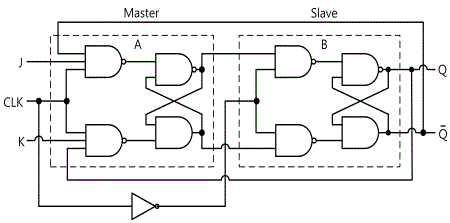
Due to the feedback connection of JK flip-flop, if the CP still remains after (when J=K=1) the output takes the complement, it takes the complement again and again repeatedly and successively. To avoid this undesirable status, the duration of CP should be longer than the propagation delay time when the signal goes through the flip-flop. This is very limited because the operation of circuit depends on the width of pulse. To solve this problem, Master-Slave JK flip-flop in fig.14-5 is used.
1. Circuit-2 of M14 shows JK F/F. If the input switch is ON, it means High, and if it is OFF, it means Low.
2. Connect 2c terminal and Manual Pulse Output, apply JK input as table 14-2 and press Manual Switch once. Record the output status in the table.
3. Change the JK input as table 14-2 and record the output value according to the lighting of LED1 and LED2 on the output terminal.
tab1Experiment 14-2.1 JK-FF(Flip Flop) Circuit Experiment (Circuit-2 of M14)
1.Connection
1.Circuit Connection
In Circuit-1 of M14, connect between 1a terminal and 2c terminal of Circuit-2 with yellow line.
2.Power connection is internally connected.
2.Wiring Diagram
3.Measurement
- 1Use Circuit-1 and Circuit-2 of M14.
Using switch S1 of Circuit-1 and switch S1 and S2 of Circuit-2, express the status of ON as “H”, and that of OFF as “L”. Express the status when the output LED is on as “H”, and when it is off as “L”.
- 2Apply the input of J, K according to table 14-2, and record the output of Q, Q following the lighting of LED-1, LED-2 when turning on(L→H) the switch S1(CLK) of Circuit-1 and when turning off(H→L).
Experiment Result Report
1. Experiment Result Table
2. Review and Explanation
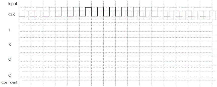
1) With the result in table 14-2, draw a timing chart.


