PART15Combination Logic Circuit
Experiment 3 :Multiplexer / Demultiplexer
Theory
Multiplexer
Multiplexing means to send many information devices through small number of channels or lines. A digital multiplexer is a combination circuit that chooses one input lines among many and connects it to the output line. According to the value of the choice lines, a special input line is chosen. In general case, it is composed of 2n input lines and n choice lines. Here, according to the bit combination of the choice lines, one among many inputs is chosen.
Fig.15-6(a) is an example of 4×1 multiplexer. Each of 4 input lines, and each line from I0 to I3 becomes one input of each AND gate. The choice lines S1 and S0 operate to choose AND gate when special operation is needed. The function table in fig.15-6(b) is the list of input/output path for each of the possible bit combinations of choice lines. When this MSI function is used for the digital system design, it is expressed as the block diagram in fig.15-6(c). To explain the circuit operation, let’s take a look at the case when S1S0=10. In case of AND gate(A-2) concerning the input I2, two inputs become “1” and the remaining input becomes I2. At least one input of the other 3 AND gates becomes “0” so the outputs all become “0”. Therefore, the output of OR gate becomes same as I2. That is, OR gate is the path that connects the chosen input to the output. The multiplexer chooses one among many inputs and delivers the binary information of the chosen input line so it is called data selector.
Demultiplexer
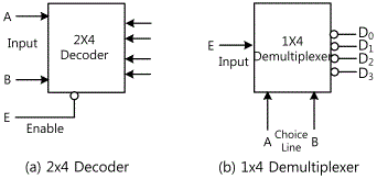
The decoder that has one enable input functions as a demultiplexer. The demultiplexer is the circuit that receives the information in one line and sends the information by choosing one line among 2n possible output lines. According to the value of n choice lines, special output line is chosen for the demultiplexer. The decoder in fig.15-7 is operated as a demultiplexer if E is the input line and A and B are the choice lines. This can be seen in fig.15-8(b). The input variable E has paths that go through all output line. However, the input information is connected to only one output line that is determined by the binary value of A and B. This can be proved by the truth table of this circuit in fig.15-7(b). For example, if the choice line AB=10, D2 becomes same as input E and all the other outputs become “1”. The calculations of decoder and demultiplexer are earned from the same circuit so the decoder that has enable input can be considered the decoder or demultiplexer. It is the enable input that makes the circuit as demultiplexer and the decoder itself uses AND, NAND or NOR gates. Decoder/demultiplexer circuits can be connected together to form a bigger decoder circuit.
Experiment Process
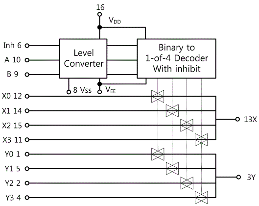
1. Circuit-3 of M-15 shows a dual 4-channel analog multiplexer. Fig.15-9 is its block diagram.
2. When inhibit and the input of choice line is as in fig.15-5, measure and record the output X, Y in the relevant column.
tab1Experiment 15-3.1 Multiplexer/Demultiplexer Circuit Experiment (Circuit-3 of M15)
Multiplexer Circuit
1.Connection
1.Circuit Connection
In Circuit-3 of M15, connect between X0 and Q0 terminals of digital output on front panel, between X1 and Q2 terminals, between X2 and Q3 terminals, between X3 and Q3 terminals with yellow lines, and between Y0 and Q4 terminals, between Y1 and Q5 terminals, between Y2 and Q6 terminals, between Y3 and Q7 terminals with blue lines.
In Circuit-3 of M15, connect between X and I0 terminals of digital output on front panel, between Y and I1 terminals with yellow lines.
2.Power connection is internally connected.
2.Wiring Diagram
3.Measurement
- 1Circuit-3 of M-15 is a circuit that represents a dual 4-channel analog multiplexer/demultiplexer. Fig.15-9 is its block diagram.
- 2Measure the output X, Y.
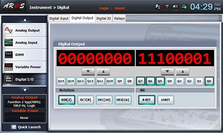
Choose digital i/o at Touch LCD panel, click Digital Output tab, choose at Bit, and click Q0→X0 … Q7→Y3 corresponding to the input data of table 15-5. (For example, if X0=1, X1=0, X2=0, X3=0, Y0=0, Y1=1, Y2=1, Y3=1, choose as Q0=1, Q1=0, Q2=0, Q3=0, Q4=0, Q5=1, Q6=1, Q7=1.)
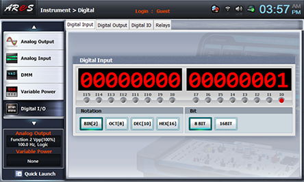
Click Digital Input tab at Touch LCD panel, choose at Bit, and when Inhibit and the input of choice line is same as Control in table 15-5, measure the indicated value of output X, Y and record the result in the relevant column. (I0 is the output X of X channel and I1 is the output Y of Y channel.)
Repeat the process above with the input data of table 15-5, measure and record the result in the relevant column.
Demultiplexer Circuit
1.Connection
1.Circuit Connection
In Circuit-3 of M15, connect between X0 and I0 terminals of digital output on front panel, between X1 and I2 terminals, between X2 and I3 terminals, between X3 and I3 terminals with yellow lines, and between Y0 and I4 terminals, between Y1 and I5 terminals, between Y2 and I6 terminals, between Y3 and I7 terminals with blue lines.
In Circuit-3 of M15, connect between X and Q0 terminals of digital output on front panel, between Y and Q1 terminals with yellow lines.
2.Power connection is internally connected.
2.Wiring Diagram
3.Measurement
- 1Circuit-3 of M-15 is a circuit that represents a dual 4-channel analog multiplexer/demultiplexer. Fig.15-9 is its block diagram.
- 2Measure the output X0, X1, X2, X3, Y0, Y1, Y2, Y3.
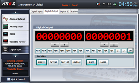
Choose digital i/o at Touch LCD panel, click Digital Output tab, choose at Bit, and click the input data of table 15-5 corresponding to X, Y. (For example, if X=1, Y=0, choose as Q0=1, Q1=0.)
Click Digital Input tab at Touch LCD panel, choose at Bit, and when Inhibit and the input of choice line is same as Control in table 15-5, measure the indicated value of output X1~X3, Y4~Y7 and record the result in the relevant column. (I0~I3 are the output for the input X of X channel and I4~I7 are the output for the output Y of Y channel.)
Experiment Result Report
1. Experiment Result Table
2. Review and Explanation
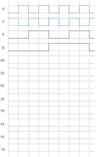
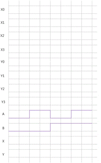
1) With the results in table 15-5, 6, draw the timing chart.
