PART10Power Supply Circuit
Experiment 3 :Variable Voltage Regulator
tab1
Experiment 10-3.1
Variable Constant Voltage Circuit Experiment Using Transistor
(In Circuit-1, 2 , 3 of M10, compose a variable constant voltage circuit by transistor as in fig 10-13.)
1.Connection(Circuit -1,2,3 of M-10)
1.Circuit Connection
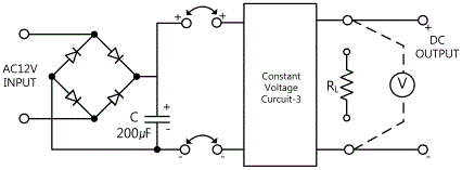
Variable Constant Voltage Circuit; Connect between 1j terminal of Circuit-1 and 3a terminal of Circuit-3 with red line, and between 1n terminal and 3b terminal of Circuit-2 with black line.
2.Power Connection
Connect between Variable Power V1 terminal on the left of M10 board and 1a terminal of Circuit-1 with red line, and between COM terminal and 1b terminal with black line.
3.Measuring Instrument Connection
Voltmeter Connection
Input Voltage Measurement Connection(Input Voltage): Connect between 3k terminal of Circuit-3 and A+ terminal of Signal Input CH A on the front panel of Multimeter with red line, and between 3l terminal and A- terminal with black line.
Input Voltage Measurement Connection(Ripple Effective Voltage): Connect between 3k terminal of Circuit-3 and B+ terminal of Signal Input CH A on the front panel of Multimeter with red line, and between 3l terminal and B- terminal with black line.
2.Wiring Diagram
3.Measurement
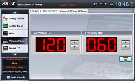
- 1Choose variable_power at Touch LCD panel, and click 3 Phase AC Range Power tab.
Click at the right of AC Voltage indication window and make it as 12.0V.
Click and apply the output of 3 Phase AC Range Power to the input of Circuit-1.
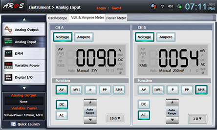
- 2Measure the output ripple effective voltage and ripple rate with no-load when setting the output voltage as 6V.
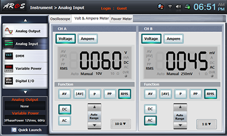
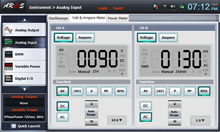
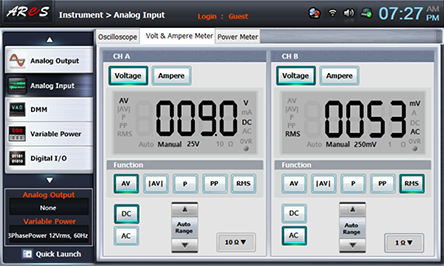
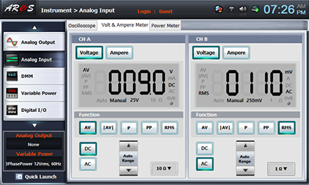
Choose analog input at the front panel, choose Volt & Ampere Meter tab and click , , at CH A, and , , at CH B.
Adjust the variable resistance R4 for output voltage adjustment, and make the voltage of CH A as 6V, then record the ripple effective output voltage measured in CH B in the relevant column of table 10-5.
- 3Measure the output ripple maximum voltage, effective voltage and ripple rate when the output voltage is set up as 6V.
120Ω Load Connection: Connect between 2j terminal of Circuit-2 and 3k terminal of Circuit-3 with red line, and between 2l terminal and 3l terminal with black line.
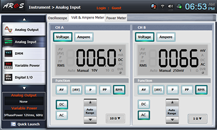
Adjust the variable resistance R4 for output voltage adjustment, and make the voltage of CH A as 6V, then record the ripple effective output voltage measured in CH B in the relevant column of table 10-5.
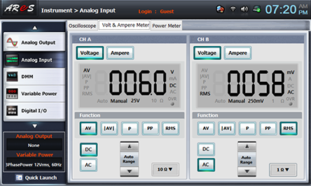
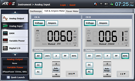
- 4Measure the output ripple effective voltage and ripple rate with load and with no-load when changing the output voltage as 7.5V and 9V.
Execute the measurement process 2) 3) and record the measured value in the relevant column of table 10-5.
After the measurement, choose variable power and click to cut off AC 12V output.
Experiment 10-3.2
Variable Constant Voltage Circuit Experiment Using OP-Amp
(Using Circuit-1, 2, 4 of M10, compose a variable constant voltage circuit
by OP-Amp as in fig 10-14.)
1.Connection(Circuit -1,2,4 of M-10)
1.Circuit Connection
Variable Constant Voltage Circuit; Connect between 1j terminal of Circuit-1 and 4a terminal of Circuit-4 with red line, and between 1n terminal and 4b terminal of Circuit-2 with black line.
2.Power Connection
Connect between Variable Power V1 terminal on the left of M10 board and 1a terminal of Circuit-1 with red line, and between COM terminal and 1b terminal with black line.
3.Measuring Instrument Connection
Voltmeter Connection
Input Voltage Measurement Connection(Input Voltage): Connect between 4i terminal of Circuit-4 and A+ terminal of Signal Input CH A on the front panel of Multimeter with red line, and between 4j terminal and A- terminal with black line.
Input Voltage Measurement Connection(Ripple Effective Voltage): Connect between 4i terminal of Circuit-4 and B+ terminal of Signal Input CH A on the front panel of Multimeter with red line, and between 4j terminal and B- terminal with black line.
2.Wiring Diagram
3.Measurement
- 1Execute 1), 2), 3), 4) of [Variable Constant Voltage Circuit using Transistor, Fig. 10-13 Circuit]>3. Measurement and record it in the relevant column of table 10-5.
How to connect 120Ω load: Connect between 2j terminal of Circuit-2 and 4i terminal of Circuit-4 with red line, and between 2l terminal and 4j terminal with black line.
4.Calculation
1. Calculate the ripple rate by the formula below.
![Ripple Rate= (Ripple Voltage (V_rms))/(DC Output Voltage (V_AV))×100[%]](../image/part10/c12.gif)


