PART1DC Circuit
Experiment 2 : Series Connection Circuit and Parallel Connection Circuit of Resistance
Theory
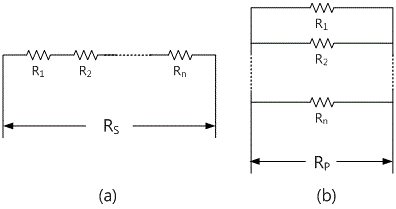
As in Fig. 1-7(a), when more than 2 resistances are connected in series and the combined resistance is RS, it can be formularized as formula 1-3 below.

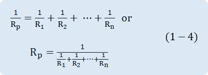
As in Fig. 1-7(b), when more than 2 resistances are connected in parallel and the combined resistance is RP, it can be formularized as formula 1-4 below.

As seen in the formulae above, if the resistance is connected in series, the combined resistance increases, and if connected in parallel, the combined resistance decreases.
Experiment Process
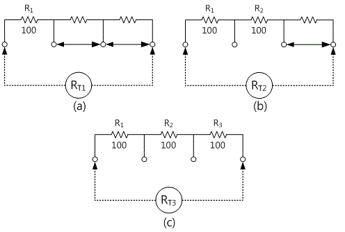
tab1Experiment 1-2.1 Series Connection of Resistance (In Circuit-2 of M-01, compose the circuit as Fig. 1-8(a), (b), (c).)
1.Connection(Circuit-2 of M-01)
1.Circuit Connection
Connect between 2b terminal and 2c terminal, and between 2c terminal and 2d terminal of Circuit-2 with yellow lines.
2.Resistance Meter Connection
Connect between 2a terminal of Circuit-2 and High terminal of Mutlimeter on the front의 panel with red line, and between 2b terminal and Low terminal with black line.
2.Wiring Diagram
RT2 Measurement
RT3 Measurement
3.Measurement
- 1Choose dmm at the left menu of Touch LCD panel and click at Digital Multi Meter window, and then the measured value will appear. Record this in experiment 2-1 of table 1-2. (RT1 Measurement)
- 2Remove the connecting line between 2b terminal and 2c terminal of Circuit-2, and record the measured data appeared on Digital Multi Meter window in experiment 2-1 of table 1-2. (RT2 Measurement)
- 3Remove the connecting line between 2c terminal and 2d terminal of Circuit-2, and record the measured data appeared on Digital Multi Meter window in experiment 2-1 of table 1-2. (RT3 Measurement)
4.Calculation
1. Calculate total resistance of 2a-2d’s both ends from Measurement 3) and 4) and record it in Fig. 1-8 of table 1-2. (RT2, RT3 Calculation)
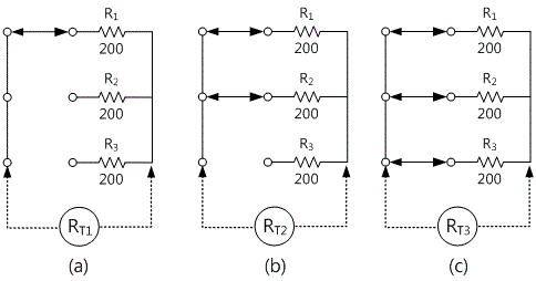
Experiment 1-2.2 Series Connection of Resistance (In Circuit-2 of M-01, compose the circuit as Fig. 1-9(a), (b), (c).)
1Connection(Circuit-2 of M-01)
1.Circuit Connection
Connect between 2e terminal and 2h terminal of Circuit-2 with yellow line.
2.Resistance Meter Connection
Connect between 2l terminal of Circuit-2 High terminal of Multimeter on the front panel with red line, and between 2k and Low terminal with black line.
2.Wiring Diagram
RT2 Measurement
RT3 Measurement
3.Measurement
- 1Choose dmm at the left menu of Touch LCD panel and click at Digital Multi Meter window, and then the measured value will appear. Record this in Fig. 1-9 of table 1-2. (RT1 Measurement)
- 2Connect between 2f terminal and 2i terminal of Circuit-2 with yellow line, and record the measured data appeared on Digital Multi Meter window in Fig. 1-9 of table 1-2. (RT2 Measurement)
- 3Connect between 2g terminal and 2j terminal of Circuit-2 with red line, and record the measured data appeared on Digital Multi Meter window in Fig. 1-9 of table 1-2. (RT3 Measurement)
4.Calculation
1. Calculate total resistance of 2l-2k’s both ends from Measurement 3) and 4) and record it in experiment 2-1 of table 1-2. (RT2, RT3 Calculation)


