PART11Oscillation Circuit
Experiment 3 :Colpitts Oscillator
Theory
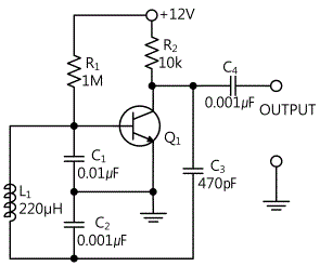
Fig.11-6 shows Colpitts oscillator. This circuit is similar to Hartley oscillator except the role of tank circuit element is changed. That is to say, capacitor is divided into two here while the inductor has single value without tab. The oscillation frequency is determined by oscillation frequency of tank circuit by series combined capacity of L1, C1 and C2.
![f_o=1/(2π√([C1C2/(C1+C2) ]L1))](../image/part11/formal11.3.gif)
There is no performance difference between Colpitts oscillator and Hartley oscillator, and the choice between them is made by convenience or economic feasibility. Also, variable output frequency of these oscillators can be earned by changing one value of tank circuit element.
Experiment Process
1. In Circuit-3 of M-11, connect between 3a-3c, and 3e-3f terminal(that is, connect L1) and compose a circuit as in fig.11-7.
2. As in table 11-3, record output frequency, output voltage, feedback voltage(voltage of C1’s both ends) and calculated frequency in the relevant columns. The feedback rate is (C2/C1)*100.
3. Remove the connection of L1 and connect between 3b-3d terminal(That is, connect L2) and repeat process 2.
tab1Experiment 11-3.1 Colpitts Oscillator Experiment (In Circuit-3 of M11, compose a circuit as in fig.11-7.)
1.Connection(In Circuit-3 of M11, experiment the circuit of fig.11-7.)
1.Circuit Connection
Connecting Inductor L1(220uH) to Circuit: Connect between 3a-3c terminal, and between 3e and 3f terminal of Circuit-3 with yellow lines.
2.Power connection is internally connected.
3.Measuring Instrument Connection
Oscilloscope and Voltmeter Connection
Output Voltage Measurement Connection: Connect between 3i terminal of Circuit-3 and A+ terminal of Signal Input CH A on the front panel of Multimeter with red line, and between 3j terminal and A- terminal with black line.
Feedback Voltage Measurement Connection(voltage of C1’s both ends): Connect between 3b terminal of Circuit-3 and B+ terminal of Signal Input CH B on the front panel of Multimeter with red line, and between 3g terminal and B- terminal with black line.
2.Wiring Diagram
3.Measurement
- 1Compose a circuit where the inductor L1(220uH) is connected.
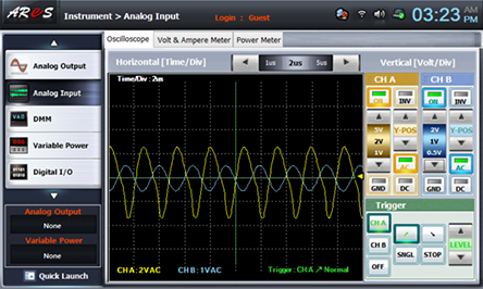
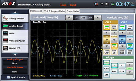
Choose analog input at front panel, draw the output wave form in oscilloscope screen, and record the output frequency and calculated frequency in the relevant columns of table 11-3. Set up the oscilloscope so that the wave form can be optimal.

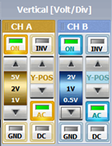
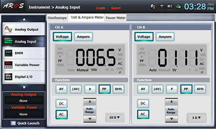
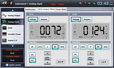
Choose Volt & Ampere Meter tab, click , , at CH A, B, and record the indicated output voltage and feedback voltage(voltage of C1’s both ends) in the relevant column of table 11-3.
(CH A : Output Voltage, CH B : Feedback Voltage)
- 2a circuit where the inductor L2(330uH) is connected.
In 1. Connection>1) Circuit Connection, remove the connection between the inductor L1(220uH) and the circuit and connect between 3b and 3d terminal of Circuit-3 with yellow line.
Execute 3. Measurement>1) process and record the measured result in the relevant column of table 11-3.
4.Calculation
1. Calculate the frequency using the formula of calculating frequency for Colpitts oscillator.
![f_o=1/(2π√([C1C2/(C1+C2) ]L1))](../image/part11/c4.gif)
Experiment Result Report
1. Experiment Result Table
2. Review and Explanation
1) Using the wave form in oscilloscope screen, compare the output frequency and calculated oscillation frequency.
![f_o=1/(2π√([C1C2/(C1+C2) ]L1))](../image/part11/c4.gif)


