PART7Amplifier Circuit(Transistor AMP)
EXperiment 3 :Darlington Amp.
Theory

If 2 npn TRs are connected as in fig. 7-7 (a), it is called Darlington-Pair(D-P) and this can be considered as one TR having 3 terminals of B, C, E. This is commonly used when very big β is needed(β ≅ β1 β2). The quantities of two TR Q1, and Q2 can be distinguished by additional number 1, 2.

Therefore,
Also,
(IB1 is small so rb1 cannot be ignored)
Therefore, the approximate small signal model of D-P becomes as fig.7-7(b). Fig 7-7 (c), (d) are CE, CC amplifier using D-P and to interpret these, substitute formulae above to relevant rules. The base current of Q1 is very small(≅IC/β1 β2) so R1, R2 can be bigger so in fig. 7-7 (c), shunt effect of R1//R2 can be ignored. In fig. 7-7 (d), the input impedance Ri from the power becomes very big. To make Ri even bigger, bootstrap bias can be used here.
In D-P of fig.7-7 (a), the base of Q2 is floating so when turned ON, the electric charge accumulated in the base area of Q2 cannot escape (through base terminal) outward when turned OFF so it cannot be operated quickly. To solve this problem, the resistance R is connected as in fig.7-8. This R also prevents reverse saturation current ICBO(1+β1) included in emitter current of Q1 from entering base of Q2. The value of R is several kΩ in D-P for small signal, and several hundreds Ω for power(if it is too small, the needed IB2 cannot be earned). Also, there are D-P of pnp, and photo-Darlington(fig. 7-9) which is more sensitive than phototransistor(β times more sensitive). These are made on one chip.
Complementary Darlington-Pairs
This is composed of the connection of pnp TR and npn TR, as in fig.7-10, and is operated as one npn TR whose β is also β1β2. The voltage between B-E is 0.7V, and the saturation voltage of Q2 cannot fall below(0.7+0.2)V. There is a chip in which resistance R is connected between B-E of Q2.
tab1Experiment 7-3.1 Darlington Amp Measurement (Compose in Circuit-4 of M-07.)
Measuring DC Characteristic of Single Transistor
1.Connection(Circuit-4 of M-07)
1.Circuit Connection
In Circuit-4 of M07 board, connect between 4q terminal and 4o terminal, between 4q terminal and 4j terminal, between 4e terminal and 4h terminal, and between 4c terminal and 4q terminal with yellow lines.
2.Power Connection
It is connected internally.
3.Measuring Instrument Connection
Plug in BNC cable to Signal Output of front panel and connect red line to 4a terminal of AC input of Circuit-4, and black line 4b terminal.
Measuring output voltage Connect between 4m terminal of Circuit-4 and Multimeter High terminal of front panel with red line, and between 4n terminal and Low terminal with black line.
2.Wiring Diagram
flash
3.Measurement
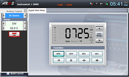
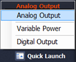
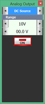
- 1Set up R1 as maximum, choose analog output at Touch LCD panel, click DC Source tab, choose DC Voltage range as and click to output DC voltage.
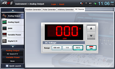
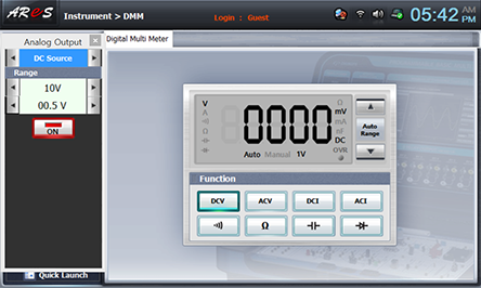
- 2Choose multimeter at Touch LCD panel and click at Function of Digital Multimeter.
- 3Choose quick launch at left bottom of Touch LCD panel, choose Analog Output and click of function to make DC Sousrce.
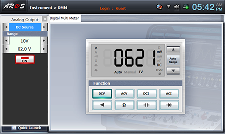
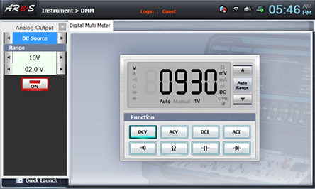
- 4Click of 0.00V to make 0.5V, and record the measured value of Digital Multimeter in Single Transistor (Re : 1KΩ) column of table 7-7.
- 5Record the measured value when connecting between 4k terminal and 4l terminal of Circuit-4 with yellow line in (Re : 1KΩ // 330Ω) column.
- 5Measure the same way as process 4)~5) above for the input voltage 1.0V, 1.5V, 2.0V and record the result in table 7-7.
- 6After all measurement is finished, click to cut off DC Source output.

Measuring DC Characteristic of Darlington Transistor
1.Connection(Circuit-4 of M-07)
1.Circuit Connection
In Circuit-4 of M07 board, connect between 4q terminal and 4p terminal, between 4f terminal and 4g terminal, between 4e terminal and 4h terminal, and between 4c terminal and 4q terminal with yellow lines.
2.Power Connection : It is connected internally.
3.Measuring Instrument Connection is same as [Measuring DC Characteristic of Single Transistor] >1. Connection.
2.Wiring Diagram
flash
3.Measurement
- 1Execute as [Measuring DC Characteristic of Single Transistor]>3. Measurement and record the result in the relevant column of table 7-7.