PART6Semiconductor-2
Experiment 4 :TRIAC Characteristic
Theory
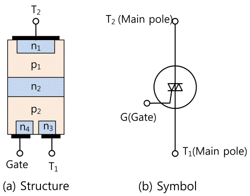
TRAIC means the device for AC control composed of 3 electrodes. It is composed by joining p type and n type semiconductors in 5 layers as in fig. 6-12(a) and attaching 2 main electrodes and 1 gate electrode. Fig. 6-12(b) is the symbol for TRAIC.
Operation Principle
It is a little bit difficult to understand the operation of TRAIC so let’s look into the conclusion first.
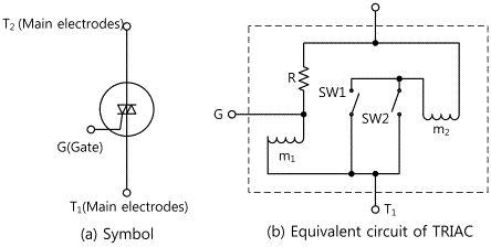
Fig. 6-13(a) is the symbol of TRAIC and fig. 6-13(b) is the equivalent circuit of TRAIC. In fig. 6-13(b), if the voltage is not supplied between G and T1 but is supplied only between T1 and T2, the current rarely flows since the resistance R is pretty big. However, if the voltage is heightened and it exceed certain limit, m1 becomes an electromagnet and pulls a piece of iron in SW1 so SW1 is turned on, and in turned-on state, M2 becomes an electromagnet by the current between T1 and T2 so SW2 is turned on.
On the contrary, if the voltage supply decreases and it becomes lower than certain limit, SW1 is turned off, and if the voltage between main electrodes gets near to 0V, the magnetism of m2 becomes weak because the current between main electrodes decrease and SW2’s the piece of iron falls by the spring, so SW2 is also off.
When power is supplied between G and T1, the current flows from (+) voltage part to (-) voltage part. And the current goes through m2 so even though the gate current is lowered to 0, m2 is still a electromagnet and it is still on unless the voltage supplied between T1 and T2 becomes 0V.
But if the voltage supplied between T1 and T2 becomes momentarily 0 when the gate current is 0, then SW2 becomes off. TRAIC is the semiconductor which operates as above.
Characteristic
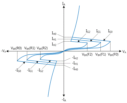
Fig. 6-14 shows I-V characteristic between main electrodes(T1, T2) when changing the gate current of TRAIC in 3 stages.
According to the characteristic curve in fig. 6-14, TRAIC shows the characteristic as inverse parallel connection of SCR.
Just as SCR, in case of TRAIC, when the gate current is not flowing, the voltage VBO for turning on is very high, and as the gate current gets bigger, VBO gets lower. However, unlike SCR which is unilateral, TRAIC is bidirectional so it is the most proper semiconductor element to control AC.
Experiment Process
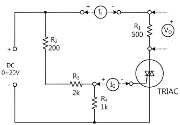
tab1Experiment 6-4.1 TRIAC Characteristic Measurement (In Circuit-4 of M06, compose a circuit as in Fig. 6-15.)
1.Connection(Circuit-4 of M-06)
1.Circuit Connection
Connect between 4f terminal of circuit-4 and T2 terminal with yellow line, and turn on the toggle switch S1.
Turn the R3 variable resistor(VR) anticlockwise to its minimum value.
2.Power Connection
Connect between V1 terminal of Variable Power on the left of M06 board and 4c terminal with red line, and between COM terminal and 4d terminal with black line.
3.Measuring Instrument Connection
Ammeter Connection
TRIAC gate current(IG) measurement : Measure by using the current measurement function of separate Digital Multimeter. Connect the red line of Digital Multimeter to 4i terminal of Circuit-4 and the black line to G terminal.
Load current(IL) measurement : Connect between Current mA/A terminal on the front panel of Multimeter and 4e terminal of Circuit-4 with red line, and between Low terminal and T2 terminal with black line.
Voltmeter Connection
Measuring voltage between T2-T1(VT2T1): Connect between A+ terminal of Signal Input CH A on the front panel and T2 terminal of Circuit-4 with red line, and between A- terminal and T1 terminal with black line.
Measuring the gate voltage of R4’s both ends(VG): Connect between B+ terminal of Signal Input CH B on the front panel and 4i terminal of Circuit-4 with red line, and between B- terminal and 4j terminal with black line.
2.Wiring Diagram
3.Measurement
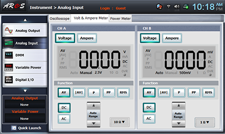
- 1Choose analog input at the left menu of Touch LCD panel, click Volt & Ampere Meter and click , , for CH A and CH B each.
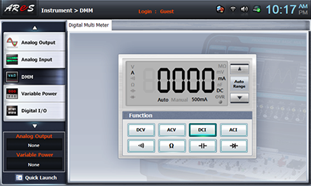
- 2Choose dmm at the left menu of Touch LCD panel and choose .
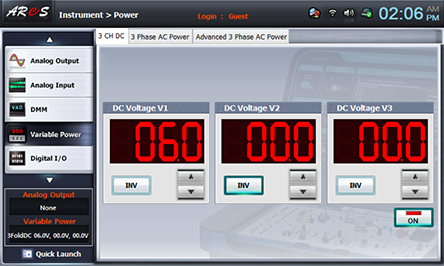
- 3Choose variable power at the left menu of Touch LCD panel and set up at 3 CH DC to make V1 as 6V with .
Click to supply DC 6V output to the circuit.
- 4Record the measured value in table 6-6.
Choose analog inputat the left menu of Touch LCD panel and record the measured values of CH A(voltage between T2-T1(VT2T1)) and of CH B(gate voltage of R4’s both ends(VG)) in the relevant column.
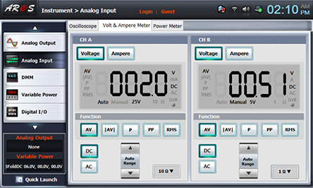
Choose dmm at the left menu of Touch LCD panel and record the measured value of load current(IL) in the relevant column.
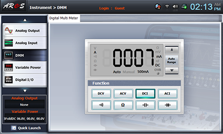
Record the measured value of TRIAC gate current(IG) measured by the current measurement function of separate Digital Multimeter in the relevant column.
TRIAC Gate Current(IG) - 5In Process 3), change the input voltage as in table 6-6, execute Process 4) and record the result.
- 6Include a lamp as the load instead of load resistance R1, execute Process 3)~5) above and record it in the relevant column of table 6-6.
Circuit Connection
Remove the connection between 4f terminal of Circuit-4 and T2 terminal and connect between 4a terminal and 4b terminal with yellow line.
Ammeter Connection
Load current(IL) measurement: Move the red connection line from Current mA/A terminal of the front panel to 4e terminal of Circuit-4 to 4f terminal, and connect between Low terminal and T2 terminal with black line.
Voltmeter Connection
Connect in the same way as 1. Connection>Voltmeter.
Wiring Diagram
- 7After the measurement, choose variable power at the left menu of Touch LCD panel and click to cutoff the power supply.
Experiment Result Report
1. Experiment Result Table
2. Review and Explanation
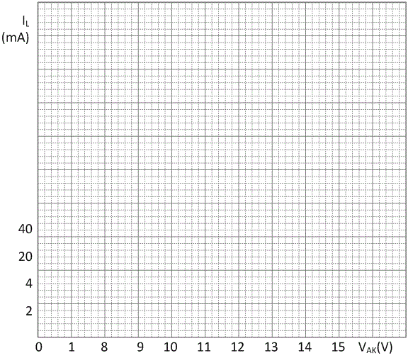
1) In the measurement value of load resistance R1 of table 6-6, draw a characteristic curve in graph 6-4 using voltage between T2-T1 of TRIAC [VT2T1]and load current [IL].
- In table 6-6 and characteristic curve of graph 6-4, indicate forward breakover voltage (VBR), holding current(IH) and switching current(Is) and record the value.
forward breakover voltage(VBR) =
holding current(IH) =
switching current(Is) =
- In case of forward breakover voltage, how much is the current flowing to the gate?
 Graph 6-4


