


PART2The principle of a ammeter, voltmeter, Ohm-Meter
Experiment Purpose
It aims to understand the measuring principle of a voltmeter, ammeter and Ohm-Meter through experiments and investigate errors occurring when designing a voltmeter, ammeter and measurement.
Experiment 1 :Voltmeter and measurement of voltage (DC Volt-meter)
Theory
Multiplier
A multiplier is a kind of resistor used to extend the voltage span by being connected to a voltmeter in series. For example, when you try to measure 100V with a voltmeter that can measure voltage of 1V, you may need the voltage divider that absorbs voltage of 99V and causes voltage drop of 1V only in the voltmeter.
In the Fig. 2-2, assuming that RM indicates a multiplier's resistance, Rm indicates a voltmeter's internal resistance, E1 indicates the voltmeter FS(Full Scale: maximum scale, i.e. maximum limit of measurement), if the voltage to be measured is n-times of the FS input voltage, the calculation method to obtain the multiplier resistance RM required to measure it is as below. First of all, the voltage Vm, VM corresponding to Rm and RM can be respectively expressed as Vm = IRm, VM = IRM. Accordingly, the circuit voltage that can be measured by connecting RM in series becomes n-times more than the case that only the voltmeter is connected. Therefore,
If the voltage to be measured through the above formula is N-times more than Vm, the multiplier's resistance RM is RM=(N-1)Rm. Thus, if you know the maximum span(or FS sensitivity) of a Meter an internal resistance, you can design the multiplier based on the range of measured voltage.
If you measure 10V by using the voltmeter with 1KΩof the internal resistance(Rm) and 1mA of FS, how much is the circuit's multiplier RM?
Voltmeter
As shown in the Fig. 2-3, most voltmeters are composed of a Current Meter and multiplying resistance connected to it in series. Generally, in the case of a DC voltmeter, the Current Meter whose FS(Full Scale) sensitivity ranges from 50μ A to 1mA is widely used and the internal resistance is approximately 100Ω ~ 1kΩ. Assuming that the input voltage is VT, the voltmeter's voltage is V1, the voltage of a multiplier's both ends is V2, VT=V1 + V2. In addition, assuming that a voltmeter's internal resistance is Rm, a multiplier's resistance is RM, V1 and V2 will have the below interaction formula.
Accordingly, when a voltmeter indicates the V1 value, the actual voltage can be measured by multiplying magnification of the span.
Assuming that the Range is set as 5V and RM is 4kΩ, input voltage is respectively 5V and 2.5V, calculate the values of V1, V2 and the actual voltage VT.(In this case, V1 : voltage of a voltmeter's both ends, V2 : voltage of a multiplier's both ends)
Experiment Process
tab1
Experiment 2-1.1 The circuit is composed in Circuit-1,2 of M-02 as shown in the Fig. 2-4
1.Wiring method(Circuit-1 of M-02)
1.Circuit wiring
Connect 1k terminal and 1f terminal of the Circuit-1 with a yellow line.
2.Power supply
Connect the com terminal and 1b(-) terminal with 0~10V input of the Circuit-1 to the Variable Power with a black line.
Connect the V1 terminal and 1a(+) terminal with 0~10V input of the Circuit-1 to the Variable Power with a red line.
3.Connecting V, A, Ω indicator (In case of using an Analog meter)
Connect Io terminal of the Circuit-1 and 2a terminal of the Circuit 2 with a red line.
Connect Ip terminal of the Circuit-1 and 2c terminal of the Circuit 2 with a black line.
4.Connecting a voltmeter
Connect (+) terminal with 0~10V input of the Circuit-1 and A+ terminal of the face panel Signal Input with a red line.
Connect (-) terminal with 0~10V input of the Circuit-1 and A- terminal of the face panel Signal Input with a black line.
2.Wiring Diagram
flash
3.Measurement
Measurement of 1.5V range multiplying resistance R1
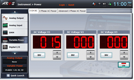
- 1Select variable power on the left menu of the Touch LCD panel.
- 2Select the 3 CH DC tab and click in the DC Voltage V1 to set 1.5V.
- 3If you click , the below screen will pop up and the output of DC 1.5V will be input to the circuit.
- 4Select analog input on the left menu.
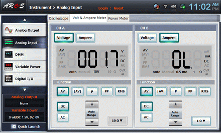
- 5If you select the Volt & Ampere Meter tab in the main screen, the below screen will pop up.
Click in the CH A and click and in Function
There may be some errors in low output voltage and measured values.
- 6Check whether the FS is 1mA in the V, A, Ω indicator.
- 7How to measure the resistance of a multiplier
Interrupt the output of DC 1.5V by clicking on the variable powerscreen and remove the power cable connected to 1a, 1b of the Circuit-1.
Select dmmon the left menu of the Touch LCD panel.
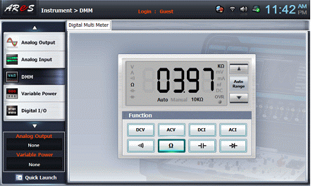
Click in the Digital Multi Meter screen and connect terminal 1c of the Circuit-1 to the Multimeter High terminal of a face panel. After connecting terminal 1f and the Multimeter Low terminal of the face panel, record the resistance R1 value measured by a multiplier in the Table 2-1.

4.Wiring diagram
Measurement of 5V range multiplying resistance R1+R2
flash
- 1Circuit wiring
Remove the connection between 1f terminal and 1k terminal of the Circuit-1 and connect 1g terminal and 1l terminal with a yellow line.
Remove the Multimeter High of a face panel and the cable connecting Low terminal and Circuit-1.
- 2Connect the power cable to 1a, 1b of the Circuit-1 and select variable power on the left menu of the Touch LCD panel.
- 3Select the 3 CH DC tab and click in the DC Voltage V1 to set as 5V, then, click .
- 4Execute the stages of 4), 5), 6) of < Measurement of 1.5V range multiplying resistance R1>.
- 5How to measure the resistance of a multiplier
Interrupt the output of DC 5V by clicking on the variable power screen and remove the power cable connected to 1a, 1b of the Circuit-1.
Select dmm on the left menu of the Touch LCD panel.
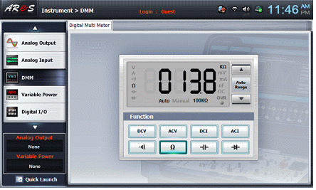
Click on the Digital Multi Meter screen and connect terminal 1c of Circuit-1 to the Multimeter High terminal of a face panel. After connecting terminal 1g and the Multimeter Low terminal of the face panel, record the resistance R1+R2 value measured by a multiplier in the Table 2-1
5.Wiring diagram
Measurement of 15V range multiplying resistance R1+R2+R3
flash
- 1Circuit wiring
Remove the connection between 1g terminal and 1l terminal of the Circuit-1 and then, connect the 1h terminal and 1m terminal with a yellow line.
Remove the Multimeter High of a face panel and the cable connecting Low terminal and Circuit-1.
- 2After connecting the power cable to 1a, 1b of the Circuit-1, Select variable power on the left menu of the Touch LCD panel.
- 3Select the 3 CH DC tab and click in the DC Voltage V1 to set as 15V, then, click Execute the states of 4), 5), 6) of Measurement of 1.5V range multiplying resistance R1>.
- 4Execute the states of 4), 5), 6) of <Measurement of 1.5V range multiplying resistance R1>
- 5How to measure the resistance of a multiplier
Interrupt the output of DC 15V by clicking on the variable power screen and remove the power cable connected to 1a, 1b of the Circuit-1.
Select dmm on the left menu of the Touch LCD panel.
Click on the Digital Multi Meter screen and connect terminal 1c of Circuit-1 to the Multimeter High terminal of a face panel. After connecting terminal 1h and the Multimeter Low terminal of the face panel, record the resistance R1+R2+R3 value measured by a multiplier in the Table 2-1.
6.Wiring diagram
Measurement of 50V range multiplying resistance R1+R2+R3+R4
flash
Experiment 2-1.2 After composing the circuit in the Circuit-1,2 of M-02 as shown in the Fig.2-4, apply input voltage of 1V, 3V, 10V, 12V to each range. Then, measure the current flowing through a meter.
1.Wiring method
Connect 1k terminal and 1f terminal of the Circuit-1 with a yellow line.
The connections of the Power supply, V, A, Ω indicator and voltmeter are shown in the Experiment 2-1.
2.Measurement method
Measuring current when 1V is applied to 1.5V range
- 1Select variable power on the left menu of the Touch LCD panel.
- 2Select the 3 CH DC tab and click in the DC Voltage V1 to set as 1V. Then, if you click , the output of DC 1.5V will be input to the circuit.
- 3After selecting analog input on the left menu, click in the CH A of a Volt & Ampere Meter and click and in the Functions.
There may be some errors in low output voltage and measured values.
- 4After recording the values of the V, A, Ω indicator in the Table 2-2, fill in measured current by moving 1f terminal to 1g, 1h, 1i
- 5Wiring diagram
flash
Measuring current when 3V is applied to 5V range
- 1Circuit wiring
After removing connection between 1f terminal and 1k terminal of the Circuit-1, connect 1g terminal and 1l terminal with the yellow line
- 2Select variable power on the left menu of the Touch LCD panel.
- 3Select the 3 CH DC tab and click in the DC Voltage V1 to set as 3V. Then, if you click , the output of DC 3V will be input to the circuit.
- 4After selecting analog input on the left menu, check the measured voltage of the Volt & Ampere Meter CH A.
- 5After recording the values of the V, A, Ω indicator in the Table 2-2 and fill in the measured current by moving the 1g terminal to 1h, 1i.
- 6Wiring diagram
flash
Measuring current when 10V is applied to 15V range
- 1Circuit wiring
Remove the connection between 1g terminal and 1l terminal of the Circuit-1 and then, connect the 1h terminal and 1m terminal with a yellow line.
- 2Select variable power on the left menu of the Touch LCD panel.
- 3Select the 3 CH DC tab and click in the DC Voltage V1 to set as 10V. Then, if you click , the output of DC 10V will be input to the circuit.
- 4After selecting analog input on the left menu, check the measured voltage of the Volt & Ampere Meter CH A.
- 5After recording the values of the V, A, Ω indicator in the Table 2-2 and fill in the measured current by moving the 1h terminal to 1i.
- 6Wiring diagram
flash
Measuring current when 12V is applied to 50V range
- 1Circuit wiring
Remove the connection between 1h terminal and 1m terminal of the Circuit-1 and then, connect the 1i terminal and 1n terminal with a yellow line.
- 2Select variable power on the left menu of the Touch LCD panel.
- 3Select the 3 CH DC tab and click in the DC Voltage V1 to set as 12V. Then, if you click , the output of DC 12V will be input to the circuit.
- 4After selecting analog input on the left menu, check the measured voltage of the Volt & Ampere Meter CH A.
- 5After recording the values of the V, A, Ω indicator in the Table 2-2 and fill in the measured current by moving the 1i terminal to 1h.
- 6Wiring diagram
flash