


PART14Sequential Logic Circuit
Experiment 3 :Binary Counter
Theory
Binary Ripple Counter
Binary counter is the serial connection of flip-flops(T or JK type) which have the function of complement-making, that is, the output of each flip-flop is connected to the input terminal of the next flip-flop. The CP is connected to the flip-flop which stores the bit of lowest position. Fig.14-6 is the system diagram of 4 bit binary ripple counter, and 1 is input to all input terminals of J and K. The small circles expressed at CP input terminals means that the status value of flip-flop becomes complement at the falling edge( ![]() ), that is, when the input value of CP input terminal changes from “1” to”0”.
), that is, when the input value of CP input terminal changes from “1” to”0”.
To understand the operation of binary ripple counter, take a look at the counter sequence in fig.14-7. The lowest bit A1 should become a complement per every clock pulse. Whenever the value of A1 changes from “1” to “0”, the value of A2 will become the complement. Also, whenever the value of A2 changes from “1” to “0”, the value of A3 will become the complement. The case of A4 will be the same. For example, let’s investigate the transition from coefficient 0111 to 1000. The arrow in the table shows the emphasis of these transitions. A1 becomes the complement by CP. The value of A1 changes from "1" to "0" and this operates the register of A2 so A2 takes the complement. Therefore, the value of A2 changes from "1" to "0" and this makes A3 as the complement, and A3 changes from "1" to "0" and makes A4 as the complement. If it is supposed that A4 is connected to the next register with the same formula, the transition of A4’s output value cannot operate the next register. This is becomes the output value of A4 changes from "0" to "1". Therefore, it becomes 1000. The flip-flops of this counter are connected quickly one by one and change. The signal is delivered in ripple form through the counter. The ripple counter is sometimes called asynchronous counter.
Binary Down Counter
Binary down counter is the binary counter that is counted in reverse(that is, the counter that decreases from 1111 to 1110, 1101). In the down counter, the binary coefficient decreases by 1 per clock pulse. 4 bit down counter coefficient starts from the binary number of 15 and changes as 14, 13, 12, ..., 0, and goes back to 15 and decreases again. In the circuit of fig.14-7, if the outputs are withdrawn from the complement terminal Q of the flip-flop, this circuit can be used as binary down counter. If only the normal output Q of the flip-flop can be earned, the modification is needed to use the circuit as a down counter. Considering the count sequence of binary down counter, the bit of the lowest position should become the complement for every CP. Whichever bit within the sequence is, if the value of the bit lower than that changes from “0” to “1”, this bit should becomes the complement. Therefore, make all the flip-flops operate at the rising edge(that is, the flip-flop removes the small circle in CP input terminal), and use the Q as CP of the flip-flop on the next terminal. If the flip-flop operates at the falling edge, input the output Q of the previous flip-flop to DCP input terminal of each flip-flop. Then, when Q changes from 0 to 1, A changes from 1 to 0 so it operates the next flip-flop. Therefore, it can be used as a binary counter.
Asynchronous Decade(BCD) Counter
Decade counter counts 10 statuses from 0 to 9, and at least 4 bit is needed to express decimal number in binary code, and the representative decade counter is BCD.
The count sequence of deci1mal counter is similar to binary counter except it is designed to change from 9 to 0.
Fig.14-9 is the diagram of decade(BCD) counter.
The count sequence is as below.
1. The output of A flip-flop changes per every CP so make sure it can be toggled with J and K as 1.
2. The output of B flip-flop changes when the output of D flip-flop is 0 and the output of A flip-flop changes from 1 to 0, and when the output of D is 1 and that of A 1, the output of B becomes 0.
3. The output of C flip-flop changes when that of B flip-flop changes from 1 to 0.
4. The output of D flip-flop changes as 1 when those of B and C are 1 and that of A changes from 1 to 0, and when those of B and C are 0 and that of A changes from 1 to 0, it becomes 0.
Fig.14-10 shows the asynchronous decade(BCD) counter and fig.14-11 is its timing chart.
Experiment Process

1. In Circuit-3 of M-14, compose a binary ripple counter as in fig.14-12.
2. Measure the output voltage according to the number of clock using the digital multimeter as in table 14-3, and if it is High, record as 1, and if Low, as 0, change them as hexadecimal numbers and record in the relevant column. Also, check out the status of LED lamp and record “1” when it is on and “0” when off. Before applying the clock, press CL switch first and make all the outputs as”0”.
tab1Experiment 14-3.1 Asynchronous Hexadecimal/Decade Counter Circuit Experiment (Circuit-3 of M14)
Asynchronous Hexadecimal Counter Circuit
1.Connection
1.Circuit Connection
In Circuit-3 of M14, connect between 1a terminal and 2c terminal of Circuit-2 with yellow line.
Connect between 3b terminal on LED1(A) of Circuit-3 and (A) terminal on the 7-Segment Display at the center, between 3c terminal of LED2(B) and (B) terminal, between 3d terminal of LED3(C) and (C) terminal, and between 3e terminal of LED4(D) and (D) terminal with yellow lines
2.Power connection is internally connected.
3.Measuring Instrument Connection
Connect BNC cable to Signal Output on front panel, connect red lead wire to 3a(CLK) terminal of Circuit-3 on M14 board and black lead wire to 3h(GND).
2.Wiring Diagram
flash
3.Measurement
- 1In Circuit-3 of M-14, compose a binary ripple counter as in fig.14-12.
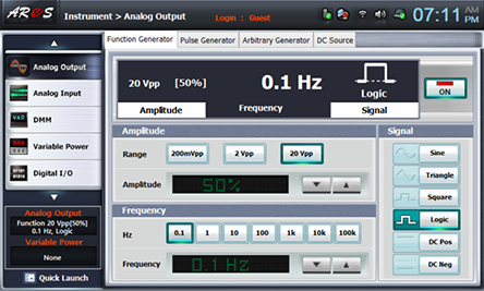
- 2Choose analog output at Touch LCD panel, and click Function Generator.
Set up Amplitude Range as , and Amplitude as amplitude 50% using .
Choose at Frequency to make frequency 0.1hz.
Set up Signal as , and click to output the logic signal 0.1Hz to Circuit-4.
- 3Record “1” when LED1(A), LED2(B), LED3(C), LED4(D) are on, and “0” when they are off in table 14-3.
Before applying the clock(CLK), press CL(Clear) once to make all the outputs as 0.
- 4Record the hexadecimal numbers displayed at 7-Segment Display in table 14-3.
Asynchronous Decade Counter Circuit
1.Connection
1.In Circuit-3 of M-14, connect between 3f-3g terminals with yellow line.(in the status of Asynchronous Hexadecimal Counter Circuit Connection)
2.Wiring Diagram
flash
3.Measurement
- 1In Circuit-3 of M-14, compose a decade up counter circuit as in fig.14-13.
Execute <Asynchronous Decade Counter Circuit>3. Measurement>3), 4) process and record the result in table 14-3.
- 2After the measurement, click at analog output of Touch LCD panel and cut off the logic pulse output to Circuit-3.
Experiment Result Report
1. Experiment Result Table
2. Review and Explanation
1) Draw a timing chart with the result of table 14-3.
<Hexadecimal Counter>
<Decade Counter>