


PART13Fundamental Logic Circuit
Experiment 3 :OR Gate / EOR Gate
Theory
In OR gate, if one of the inputs is high, the output becomes high. Fig.13-10 shows OR gate and the truth table.
The characteristic of NOR gate becomes the opposite of OR gate. Fig.13-11 shows NOR gate and the truth table.
The characteristic of 2-input EXCLUSIVE-OR (XOR) gate is that the output becomes high when the states of two inputs are different from each other. This is the difference from 2-input OR gate. Fig.13-12 shows SOR gate and the truth table.
Experiment Process
1. In Circuit-3 of M13, connect between 3b-3h terminal and compose an OR gate circuit as in fig.13-13(a). LED-1 and LED-2 indicate the input, and LED-3 indicates the output.
2. Check out the lighting of LED-3 on the output terminal by the input A and B and record the result in table 13-4.
3. In Circuit-3 of M13, connect between 3e-3i terminal and compose an XOR gate circuit as in fig.13-13(b), and record the output following the lighting of LED-4 by each input in table 13-4.
4. In Circuit-3 of M13, connect an inverter to 3b-3h terminal and compose a NOR gate circuit in fig.13-14. And record the output for each input in table 13-5.
5. In Circuit-3 of M13, connect an inverter to 3e-3i terminal and compose a XNOR gate circuit in fig.13-14. And record the output for each input in table 13-5.
tab1
Experiment 13-3.1
OR/XOR Gate Circuit Experiment
(In Circuit-3 and Circuit-4 of M13, compose circuits as in fig.13-13,14.)
2 Input OR Circuit
1.Connection
1.Circuit Connection
In Circuit-3 of M13, connect between 3b terminal and 3h terminal with yellow line.
2.Power connection is internally connected.
3.Measuring Instrument Connection
Input Voltage Measurement
Connect between 3a terminal of Circuit-3 and A+ terminal of Signal Input CH A on the front panel with red line, and between 3g terminal and A- terminal with black line.
Connect between 3c terminal and B+ terminal of CH B with red line, and between 3g terminal and B- terminal with black line.
Output Voltage Measurement
Connect between 3h terminal of Circuit-3 and High terminal on the front panel of Multimeter with red line, and between 3g terminal and Low terminal with black line.
2.Wiring Diagram
flash
3.Measurement
- 1In Circuit-3 of M13, compose a 2-input OR circuit as in fig.13-13(a).
Measure the voltage applied to OR gate input(LED1, LED2) using switch A(S1) and switch B(S2) and operating “ON”, “OFF” as in table 13-4, record the output as “ON” when LED5 is on, and as “OFF” when off. Measure and record the voltage of each case. (CH A = S1, CH 2 = S2), (LED1, LED2 are turned on when “H” is applied to A and B, and LED3 indicates the output.)
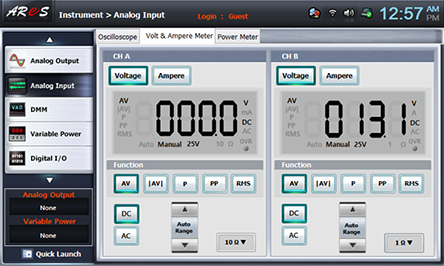
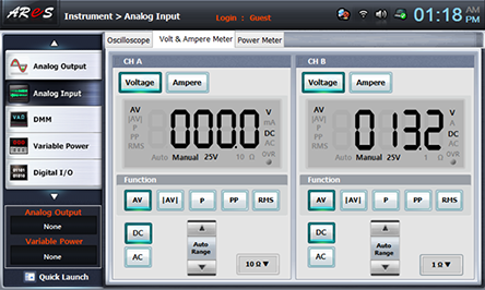
- 2Input Voltage Measurement: Choose analog input at Touch LCD panel, choose Volt & Ampere Meter tab, click , , at CH A and CH B and record the measured output voltage in the relevant column of table 13-4. (CH A = A Input(S1), CH 2 = B Input(S2))
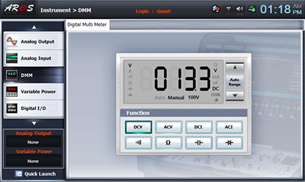
- 3Output Voltage Measurement: Choose dmm at Touch LCD panel, click and record the measured output voltage in the relevant column of table 13-4.

XOR Circuit
1.Connection
1.Circuit Connection
In Circuit-3 of M13, connect between 3e terminal and 3i terminal with yellow line.
2.Power connection is internally connected.
3.Measuring Instrument Connection
Input Voltage Measurement
Connect between 3d terminal of Circuit-3 and A+ terminal of Signal Input CH A on the front panel with red line, and between 3g terminal and A- terminal with black line.
Connect between 3f terminal and B+ terminal of CH B with red line, and between 3g terminal and B- terminal with black line.
Output Voltage Measurement
Connect between 3i terminal of Circuit-3 and High terminal on the front panel of Multimeter with red line, and between 3g terminal and Low terminal with black line
2.Wiring Diagram
flash
3.Measurement
- 1Circuit-3 of M13, compose a circuit as in fig.13-13(b).
Measure the voltage applied to XOR gate input(LED3, LED4) using switch A(S3) and switch B(S4) and operating “ON”, “OFF” as in table 13-4, record the output as “ON” when LED6 is on, and as “OFF” when off. Measure and record the voltage of each case. (CH A = S3, CH 2 = S4), (LED3, LED4 are turned on when “H” is applied to A and B, and LED6 indicates the output.)
- 2For input/output voltage measurement, execute [2 Input OR Circuit]>3. Measurement>2), 3) and record the result in table 13-4. (CH A = S3, CH 2 = S4)
2 Input NOR Circuit
1.Connection
1.Circuit Connection
In M13, connect between 3b terminal of Circuit-3 and 4c terminal of Circuit-4, and between 3h terminal and 4e terminal with yellow lines. Here, turn off S2 of Circuit-4.
2.Power connection is internally connected.
3.Measuring Instrument Connection
OR Gate, NOT Gate Output Voltage Measurement
Connect between 3b terminal of Circuit-3 and A+ terminal of Signal Input CH A on the front panel with red line, and between 3g terminal and A- terminal with black line.
Connect between 3h terminal and B+ terminal of CH B with red line, and between 3g terminal and B- terminal with black line.
2.Wiring Diagram
flash
3.Measurement
- 1Circuit-3 and Circuit-4 of M13, compose a NOR circuit as in fig.13-14(a).
Measure the output voltage of OR gate and NOT gate using switch S1 and switch S2 and operating “ON”, “OFF” as in table 13-5, record the output as “ON” when LED5(red) is on, and as “OFF” when off.
- 2Output Voltage Measurement: Choose analog input at Touch LCD panel, choose Volt & Ampere Meter tab, click , , at CH A and CH B and record the measured output voltage in the relevant column of table 13-5. (CH A = OR Gate Output, CH 2 = NOT Gate Output)

2 Input NOR Circuit
1.Connection
1.Circuit Connection
In M13, connect between 3e terminal of Circuit-3 and 4c terminal of Circuit-4, and between 3i terminal and 4e terminal with yellow lines. Here, turn off S2 of Circuit-4.
2.Power connection is internally connected.
3.Measuring Instrument Connection
XOR Gate, NOT Gate Output Voltage Measurement
Connect between 3e terminal of Circuit-3 and A+ terminal of Signal Input CH A on the front panel with red line, and between 3g terminal and A- terminal with black line.
Connect between 3i terminal and B+ terminal of CH B with red line, and between 3g terminal and B- terminal with black line.
2.Wiring Diagram
flash
3.Measurement
- 11) Using Circuit-3 and Circuit-4 of M13, compose a XNOR circuit as in fig.13-13(a).
Measure the output voltage of XOR gate and NOT gate using switch S1 and switch S2 and operating “ON”, “OFF” as in table 13-5, record the output as “ON” when LED6(red) is on, and as “OFF” when off.
- 2Output Voltage Measurement: Choose analog input at Touch LCD panel, choose Volt & Ampere Meter tab, click , , at CH A and CH B and record the measured output voltage in the relevant column of table 13-5. (CH A = XOR Gate Output, CH 2 = NOT Gate Output)