PART11Oscillation Circuit
Experiment Purpose
- 1.Investigate characteristics of RC oscillator.
- 2.Investigate characteristics of Wien bridge oscillator through experiment.
- 3.Investigate characteristics of Colpitts oscillator through experiment.
- 4.Investigate characteristics of Hartley oscillator through experiment.
- 5.Investigate characteristics of crystal oscillator through experiment.
Experiment 1 :RC Oscillator
Theory
If the oscillation frequency of sine wave oscillator is low frequency below 10kHz, LC oscillator is not practical. That is because it needs an inductor which has big volume and is expensive. Another way besides generating sine wave by tank circuit is using RC selective filter. Two general examples of RC selective filter are RC phase shift and Wien bridge oscillator.
Fig.11-2 is a circuit that oscillates sine wave, and if only one frequency passes through RC phase shift network that has 180° phase shift, the oscillation by this frequency is possible. If 180° phase inversion of transistor’s input/output is combined with this phase shift, the necessary condition for Barkhausen phase shift is satisfied. Therefore, the regenerative effect occurs at only one sine wave frequency so sine wave output is possible.
180° phase shift should occur at phase shift network, so at least RC terminals where maximum 90° phase shift is possible are needed. However, 4 terminals actually have smaller attenuation than 3 terminals so usually 4 terminals are used.
The attenuation of RC circuit should be compensated by the amplification of transistor so that total closed circuit gain should be bigger than “1”. However, if the gain is much bigger than “1”, the stability of circuit gets worse so the circuit gain should be adjusted to proper level so that the result becomes satisfactory. This becomes by possible, as shown in fig.11-2, by adding variable resistance to feedback path. Occasionally the transistor that has very high current gain hfe is used to compensate for the loss of RC network. The oscillation frequency of 3 terminal RC oscillator can be approximated as below if the values of 3 R and C are same.
To adjust the frequency of RC phase shift oscillator in a wide range, multiple resistances and capacitors should be adjusted so it is not used with the broad oscillator. And this adjustment can cause attenuation so the gain adjustment is required. If there is no gain adjustment, the closed circuit gain of the latter terminal falls below “1” so the oscillation stops or it becomes much bigger than “1” so it becomes unstable. In this circuit, it is general for the output signal to have about 5% of distortion level.
Experiment Process
1. Compose a circuit as in fig.11-3 using Circuit-1 of M-11. In fig.11-3, use the capacitor C of 0.001uF, the resistance R of 100kΩ, and adjust R4 so that the output frequency becomes 1/(2π√6 CR).
2. As in table 11-1, measure and record the output frequency, and calculate and record the output frequency. And measure the output voltage and record as RMS.
3. In fig.11-3, make the capacitor C as 0.002uF(connect between 1b-1e, 1c-1f, 1d-1g)and connect C9(connect between 1j-1k) and repeat process 2.
tab1Experiment 11-1.1 Phase Shift Oscillator Experiment (In Circuit-1 of M11, compose a circuit as in fig.11-3.)
1.Connection
1.Power connection is internally connected.
2.Measuring Instrument Connection
Oscilloscope and Voltmeter Connection
Output Voltage Measurement Connection: Connect between 1i terminal of Circuit-1 and A+ terminal of Signal Input CH A on the front panel with red line, and between 1l terminal and A- terminal with black line.
2.Wiring Diagram
flash
3.Measurement
- 1Use the capacitor C of 0.001㎌, the resistance R of 100㏀ and adjust R4 so that the output voltage becomes maximum.
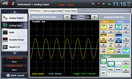
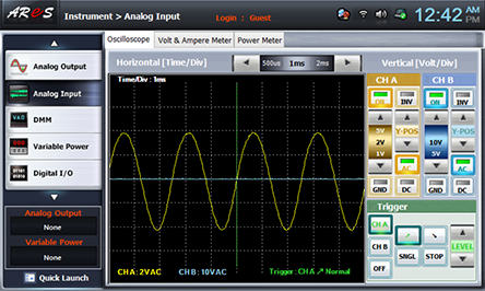
Choose analog input at front panel, adjust R4 to make maximum output by referring to the wave form of Oscilloscope screen and draw the output wave form in table 11-1, calculate and record the frequency, and calculate and record the output frequency by the formula.
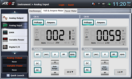
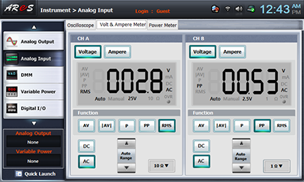
Choose Volt & Ampere Meter tab, click , , at CH A and record the indicated output voltage in the relevant column of table 11-1.
- 2Use the capacitor C of 0.002㎌, the resistance R of 100㏀ and adjust R4 so that the output voltage becomes maximum.
In Circuit-1 of M11, connect between 1b-1e, between 1c-1f, and between 1d-1g terminals with yellow lines.
Wiring Diagram
flash
Execute the measurement process1) above and record the result in the relevant column of table 11-1.
4.Calculation
1. Calculate the frequency by using the formula of frequency in phase shift oscillation circuit.